


By reading this article, you will learn more about the Beamforming Antennas, how they work and are tested.
1. What are beamforming Antennas?
2. What is the difference between 5G passive and active antennas?
3. Basic principles of Beamforming
4. Analog and Digital beamforming
5. Smart Antennas
6. How are Beamforming Antennas tested?
7. References
What are beamforming Antennas?
Beamforming is the most commonly used method by a new generation of smart antennas. In this method, an array of antennas is used to “steer” or transmit radio signals in a specific direction, rather than simply broadcasting energy/signals in all directions inside the sector. In this method, multiple smaller antennas control the direction of the combined transmitted signal by appropriately weighing the magnitude and phase of each of the smaller antenna signals. In this technique, the phase and amplitude of the transmitted signal of each component antenna are adjusted as needed, resulting in a constructive or destructive effect, concentrating the total transmitted signal into a targeted beam.
Beamforming antennas are becoming increasingly common and have many applications e.g. in radars, and especially in the field of telecommunications. Beamforming as a technology has been around since well before 5G, since of the early days of mobile broadband. The method by which beamforming is achieved is growing increasingly more sophisticated, partly thanks to contemporary Massive MIMO antennas. Used since 3G, MIMO technology lets radio signals to be sent and received using several antennas. Massive MIMO antennas have many more component antennas (around 100) that allow them to transmit radio signals more efficiently. This allows for very high data rates.
What is the difference between 5G passive and active antennas?
Passive antennas are built entirely out of passive elements, whereas active antenna systems contain active components that control the antenna performance to maintain the best possible operation for any conditions. While passive antennas play a role in 5G networks, it is active antennas that enable beamforming through Massive MIMO technology. Active antennas support many different user cases with a need for increased signal strength or configurable antennas.
5G has established new standards for wireless communications, expanding the frequency ranges above the frequencies used by previous generations. The technology developed for 5G includes FR1, which operates below 6 GHz, and FR2, which includes bands above 24 GHz and extremely high frequency range above 50 GHz.
Basic principles of Beamforming
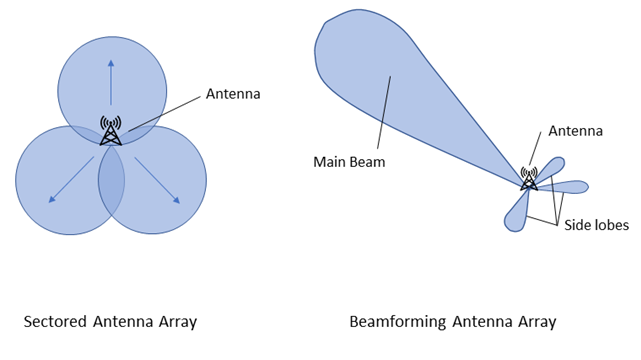
A beamforming antenna uses multiple antenna elements to control the direction of a wave-front. By changing the phase of the individual signals in an antenna array the beam can be formed at an angle. The plane wave can then be directed in the desired direction.
When pointing the resulting beam at a target receiving antenna in the far-field, the distance from each element of the array to the target is slightly different. Also, the path length difference for each signal is d*cos(θ), where is the angle of arrival for the individual signal. To offset this difference, so that each signal arrives at the same phase, phase shifters are applied to each element, resulting in a coherent beam in the far-field. This is called coherent combining.
Due to the constructive and destructive effects of the combining individual signals in a directional antenna, the resulting radiation pattern will have many lobes of differing field strengths at various angles. In this case, the signal strength reaches a maximum, separated by nulls, angles at which the radiation falls to zero. The main lobe with the highest power is the intended beam, while the other, smaller side lobes are usually unwanted as they radiate undesired radiation in unnecessary directions.
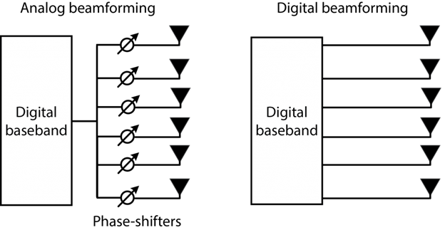
Analog and Digital beamforming
There are many methods to implement antenna beamforming. The three main categories of analog, digital and hybrid beamforming are briefly introduced in the next few chapters:
Digital beamforming: In this method, each antenna element has its own transceiver and data converters. This makes it possible to generate several sets of signals and apply them to the antenna elements. The antenna array is able to handle multiple data streams and form multiple directed beams at the same time. With the ability to form multiple beams, this antenna type can transmit data simultaneously to multiple receivers, serving multiple users in a highly efficient manner. Digital antenna beamforming requires more hardware and signal processing resources but is generally a more adaptable approach.
Analog beamforming: Using the analog method, there is only a single set of data converters for the entire antenna, and only a single data stream is handled. This means only one beam per set of antenna elements can be formed. The data stream is split into several signal paths, as many as there are antenna elements, and each signal path is fed through a phase shifter and sent to the individual antenna element. Analog beamforming increases the gain of the antenna array, providing additional coverage. Downside of the analog beamforming is that the whole frequency band has same beam direction.
Hybrid beamforming: This approach combines the two methods above. The antenna array has subarrays of analog beamforming, as well as digital combining of the subarray signals. This reduces energy consumption and design complexity, making it more generally cost-effective.
Smart Antennas
Smart antennas are able to analyse their operating environment and alter their antenna pattern, adjusting their functions appropriately to changing conditions. This enables smart antennas to achieve improved performance. The development of smart antenna technology is supported by the deployment of new applications such as software-defined radio, cognitive radio, MIMO, and many others.
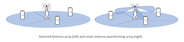
Smart antennas include artificial intelligence, capable of signal processing, and can detect the direction of incoming and outgoing signals. They also use beamforming to change transmitted antenna pattern as well as the direction of the transmitted signal. With the extensive amount of functionality that is required from smart antennas, two major methods of smart antenna technology have been developed. Both systems have the same basic function and can provide directivity. However, they differ in cost and complexity, and suited to different applications:
Switched beam smart antennas: Switched beam smart antennas are designed to combine the signals of multiple antennas to create several predetermined fixed beam patterns. These beams are then steered towards one or several specific directions. The SBA can select the most suitable one for the given situation. This method is not as flexible, but it is a simple, robust design that is suitable for a lot of uses.
Adaptive array smart antennas: An adaptive antenna array can continuously steer the beam in any direction and has a more adaptable radiation pattern. Adaptive arrays require more intelligence and can better determine the surrounding environment. They are usually more accurate and efficient compared to SBAs since they can better suppress unwanted beams. In comparison to multi-user MIMO networks, massive MIMO is using a high number of antennas in the base station. It can be seen as a direct extension of Multi-user MIMO. Read more about multi-user MIMO and massive MIMO.
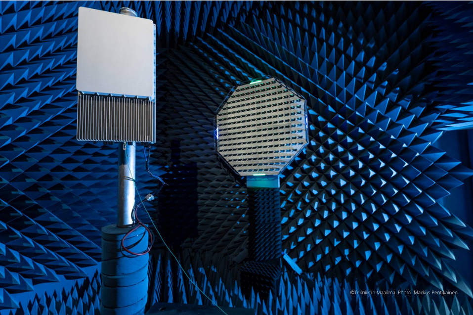
How are Beamforming Antennas tested?
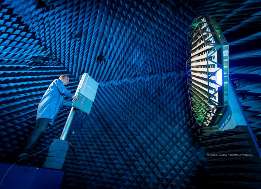
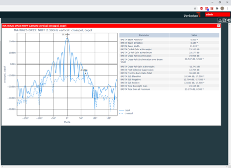
In this article, testing of large beamforming antenna arrays is considered. Typical example is a 4G or 5G base station utilizing a beamforming active antenna array. Testing the OTA performance of beamforming antennas can be divided into two main classes, namely passive and active antenna testing. After testing beamforming antennas, our AntView® tool makes analyzing and storing antenna measurement results easier and more efficient by visualizing and organizing data.
We are offering a free demo access to our AntView® tool. You can find instructions how to use AntView® and how to get the AntView® demo use access from our AntView® Demo -news.
1. Passive Antenna Testing
Passive antenna testing uses an OTA test method where the test signal is fed directly to the antenna array, and the outputted RF signal is then measured. The DUT is typically only the passive antenna array without any active radio unit. This makes passive antenna testing straightforward and delivers easily comparable results. Passive antenna performance measurements mainly entail measuring characteristics such as gain, directivity, efficiency, side lobe ratios etc. Typically either 2D cross sections or full 3D pattern is measured. Each antenna port is measured either separately and the beam is formed in postprocessing using mathematical port weights, or a beamforming combiner device is used to produce the desired beam at measurement time.
2. Active Antenna Testing
For testing active antennas, a similar environment is used. However, in an active antenna, the antenna ports are embedded in the device. Most of the RF signal generation steps are performed in the radio unit itself. The testing has to be performed in active mode, so that the DUT is in signaling mode, with the radio unit and antenna array operating as it would in the real network. Due to the tight integration of the radio unit and active antenna array, more and more parameters that were traditionally measured in a conducted test setup must be tested in radiated conditions. On the FR1 frequency range, typical parameters measured over the air include the transmitted power and sensitivity of the base station. In addition to this, on FR2 all the RF parameters must be evaluated over the air. These include parameters such as EVM, ACRL, blocking, selectivity, spurious emissions, among many others.
3GPP Test Methods
At this time, there are multiple OTA measurement system types described in 3GPP (3rd Generation Partnership Project) test standard for testing beamforming active antennas. The standards defining conformance evaluation of beamforming active antennas are 3GPP TS 38.141-2 and 3GPP TS 37.145-2. These standards refer to 3GPP TR 37.941, which gives definitions for the test system types, procedures and uncertainty calculation methods. The main test system types are indoor anechoic chamber, compact antenna test range (CATR) and plane wave synthesizer.
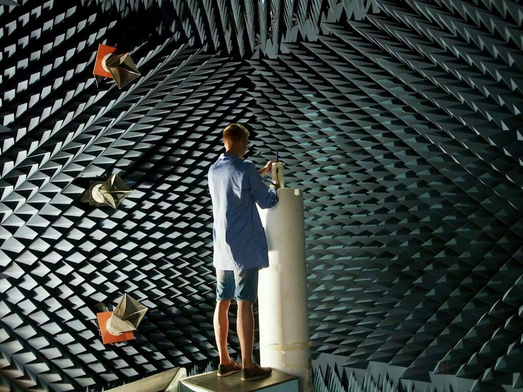
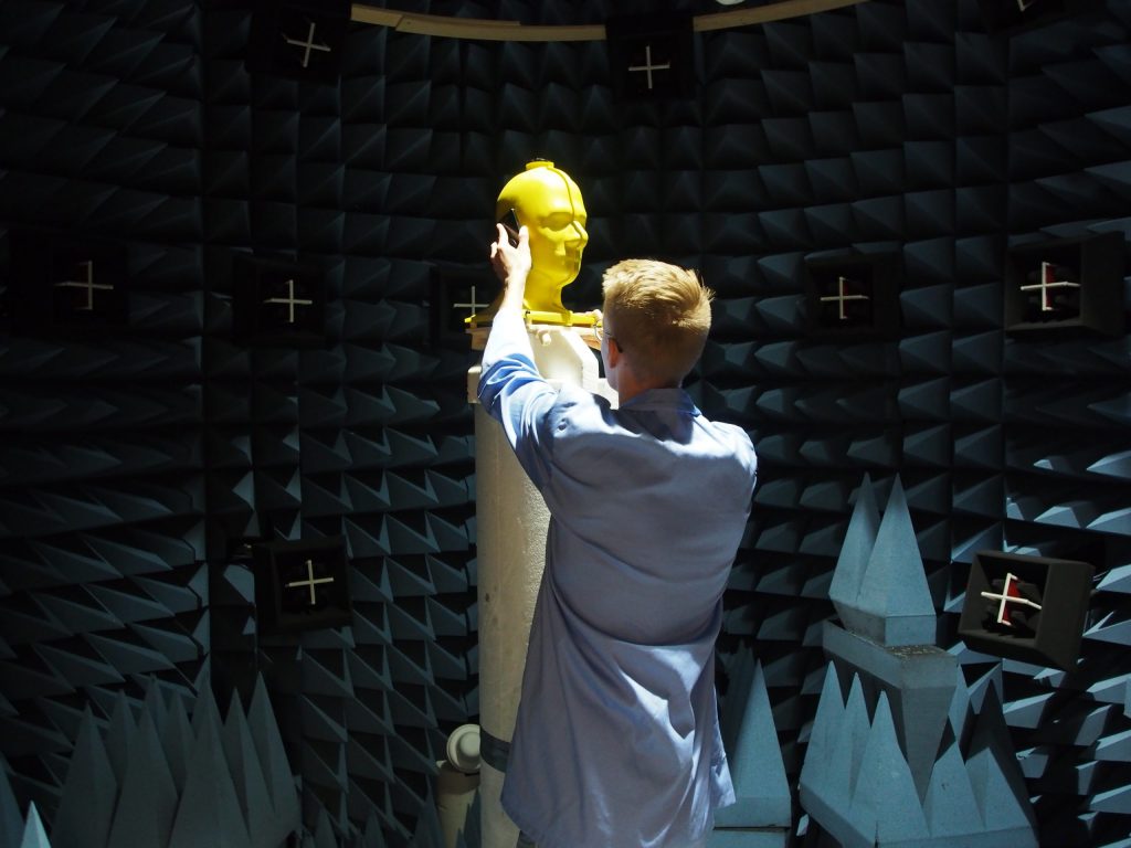
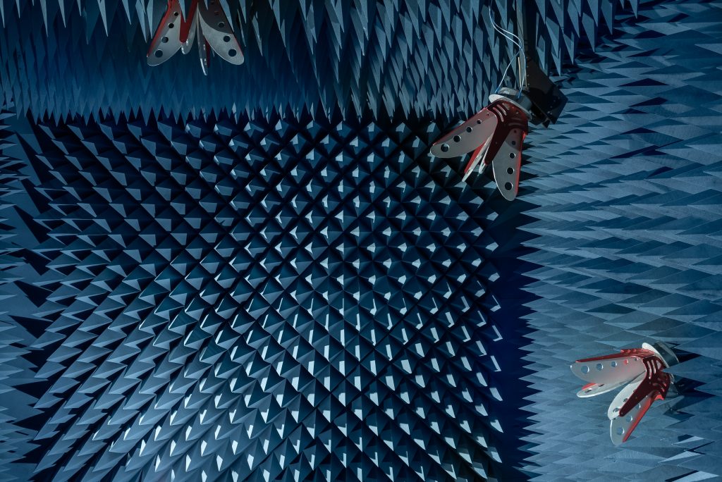
1. Indoor anechoic chamber
The indoor anechoic chamber refers to a chamber in which the measurement distance is sufficiently large so that the DUT is tested in a far field condition, defined by the Fraunhofer distance. The size of the required test chamber can be quite large, depending on the frequency and DUT size.
2. Compact antenna range
The compact antenna test range (CATR) test system utilized a radio frequency reflector. The radiated signals are reflected from a parabolic reflector to create the far-field condition at distance shorter than required by the Fraunhofer criterion.
3. Near to far-field method
An alternative approach is antenna near-field measurements using a near-field to far-field (NF-to-FF) conversion, where the far-field characteristics are calculated using software and necessary transformation algorithms. This approach considerably reduces the required distance to measure far-field characteristics. This allows test labs to reduce the size of their anechoic chambers without losing measurement accuracy. Verkotan provides ’s active near-field-to- far-field antenna test service for the whole FR1 frequency range due to our wide bandwidth horn antenna setup. We can test a full range of antenna characteristics and offer our customers tests regarding antenna patterns.
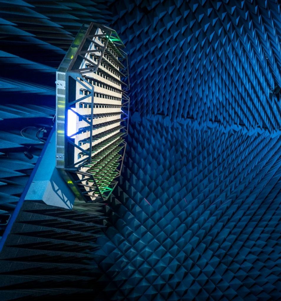
4. Plane Wave Synthesizer
In a test system utilizing plane wave synthesis, the far field is produced at the test zone using a plane wave converter. A plane wave converter is a phased antenna array, which acts as a replacement for a traditional test system antenna. The test signals are fed through the antenna elements of the converter, and are the amplitude and phase of each element in the array is controller so that a plane wave field is produced at the test zone.
Verkotan uses R&S PWC200 plane wave converter for Verkotan`s Plane Wave Synthesis Active Antenna Test Service, which is available for BW 2,3-3,8GHz covering the most important FR1 5G bands. gNB sizes up to one meter can be tested. Plane Wave Converter (PWC) is for 5G massive MIMO base station testing.
Beamforming in a nutshell
Beamforming has become a standard technology in boosting the data rates of wireless communication. It forms the basis of massive MIMO technology and is in use in 5G base stations and client devices. Beamforming enables adjusting the antenna pattern shape on the fly, and thus increased adaptivity to the network conditions.
The testing of beamforming antennas brings new challenges, due to increase in integration between the radio unit and antenna, due to which more and more of test cases that were traditionally done in a conducted test setup are being done in OTA conditions. Testing of large antennas requires far field condition capability from the test system, and specialized test equipment and methods are required to achieve it, especially in active antenna testing.
Read also our other articles about OTA – Wireless Performance Testing or Cell phone waves if you want to learn more about OTA testing.
References
- https://www.electronics-notes.com/articles/antennas-propagation/smart-adaptive-antennas/what-is-smart-adaptive-antenna-technology.php
- https://www.electronics-notes.com/articles/antennas-propagation/smart-adaptive-antennas/beamforming-beamsteering-antenna-basics.php
- https://www.ofcom.org.uk/research-and-data/technology/general/emerging-tech/smart-antennas
- Massive MIMO Antennas is seen as a key technology to delivering mobile 5G | International Defense Security & Technology Inc. (idstch.com)
- https://www.metaswitch.com/knowledge-center/reference/what-is-beamforming-beam-steering-and-beam-switching-with-massive-mimo
- https://www.analog.com/en/analog-dialogue/articles/phased-array-beamforming-ics-simplify-antenna-design.html#
- 5G-OTA-article-060419-web.pdf (litepoint.com)
- Finding Ways to Test Massive MIMO 5G | Microwaves & RF (mwrf.com)
Verkotan is always happy to provide more detailed information and make a proposal how we can verify the performance of your wireless device in the global environment.
Follow our social media channels to keep up with the latest news in the world of wireless technology.
If you have any questions or need assistance, contact us. We are happy to help you!